| Tenouk C & C++ | MFC Home | ATL & ActiveX Controls 7 | Another ATL Tutorial 2 | Download | Site Index |
Another ATL Tutorial Using Visual C++ .NET part 1
|
Program examples compiled using Visual Studio/C++ .Net 2003 compiler on Windows XP Pro machine with Service Pack 2. Topics and sub topics for this tutorial are listed below. Don’t forget to read Tenouk’s small disclaimer. The supplementary note for this tutorial is the .NET early stage story.
ATL is designed to simplify the process of creating efficient, flexible, lightweight controls. This tutorial leads you through the creation of an ActiveX control, demonstrating many ATL and COM fundamentals. This tutorial does not use attributes. By following this tutorial, you will learn how to add a control to an ATL project that draws a circle and a filled polygon. You will then add a property to indicate how many sides the polygon will have and create drawing code for updating the control when the property changes. The control will then be displayed on a Web page using some VBScript to make it respond to events. The tutorial is divided into seven steps. You should perform each step in order as later steps depend on previously completed tasks. Before you begin, you should confirm that you have privileges required to register an ActiveX component on your particular computer. This is usually only a concern if you are running Visual Studio .NET over a Terminal Services connection.
Step 1: Creating the Project
This tutorial walks you step-by-step through a non-attributed ATL project that creates an ActiveX object that displays a polygon. The object includes options for allowing the user to change the number of sides making up the polygon, and code to refresh the display.
To create the initial ATL project using the ATL Project Wizard
|
|
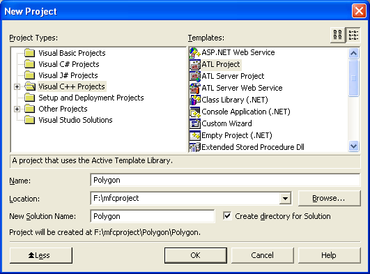
Figure 1: Visual C++ .Net, new ATL project.
The location for the source code will usually default to My Documents\Visual Studio Projects, and a new folder will be created automatically. You can change the directory if needed. This tutorial use F:\mfcproject as a location.
-
Click OK and the ATL Project Wizard opens.
-
Click Application Settings to see the options available:
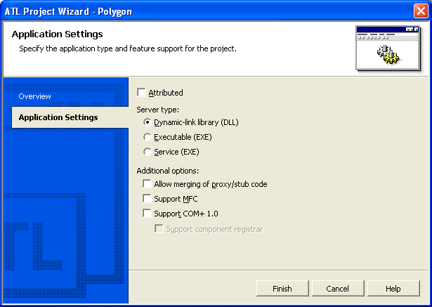
Figure 2: ATL Project Wizard – Application Settings page.
-
As you are creating a control, and a control must be an in-process server, leave the Server type as a DLL.
-
In this tutorial, you will not be using attributes, so ensure that the Attributed check box is not selected.
-
Leave the other options at their default values, and click Finish.
The ATL Project Wizard will create the project by generating several files. You can view these files in Solution Explorer by expanding the Polygon object. The files are listed below.

Figure 3: Polygon files generated by Visual C++ .Net wizard seen through Solution Explorer.
|
File |
Description |
|
Polygon.cpp |
Contains the implementation of DllMain(), DllCanUnloadNow(), DllGetClassObject(), DllRegisterServer(), and DllUnregisterServer(). Also contains the object map, which is a list of the ATL objects in your project. This is initially blank. |
|
Polygon.def |
This module-definition file provides the linker with information about the exports required by your DLL. |
|
Polygon.idl |
The interface definition language file, which describes the interfaces specific to your objects. |
|
Polygon.rgs |
This registry script contains information for registering your program's DLL. |
|
Polygon.rc |
The resource file, which initially contains the version information and a string containing the project name. |
|
Resource.h |
The header file for the resource file. |
|
Polygonps.def |
This module definition file provides the linker with information about the exports required by the proxy and stub code that support calls across apartments. For details, see COM+ Apartment Models. |
|
stdafx.cpp |
The file that will #include the ATL implementation files. |
|
stdafx.h |
The file that will #include the ATL header files. |
|
Table 1. |
|
In the next step, you will add a control to your project.
Step 2: Adding a Control
In this step, you will add a control to your project, build it, and test it on a Web page.
To add an object to an ATL project
-
In Class View, right-click the Polygon project.
-
Point to Add on the shortcut menu, and click Add Class.

Figure 4: Adding class to the ATL project.
The Add Class dialog box appears. The different object categories are listed in the tree structure on the left:
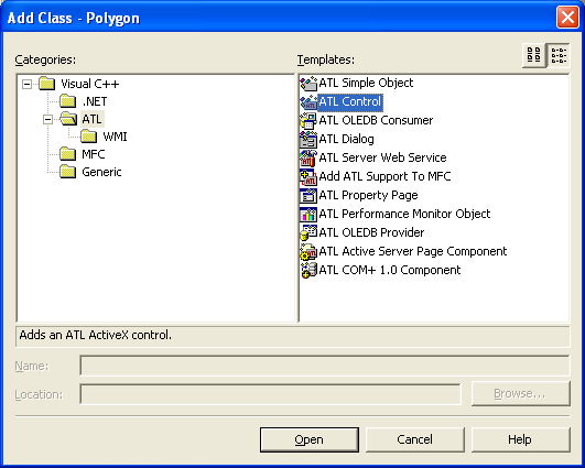
Figure 5: The Add Class dialog, adding a new class to Polygon project.
-
Expand the tree structure and click the ATL folder.
-
From the list of templates on the right, select ATL Control. Click Open. The ATL Control Wizard will open, and you can configure the control:

Figure 6: ATL Control Wizard, Names page.
-
Type PolyCtl as the short name and note that the other fields are automatically completed. Do not click Finish yet, because you need to make some changes.
The ATL Control Wizard's Names page contains the following fields:
|
Field |
Contents |
|
Short name |
The name you entered for the control. |
|
Class |
The C++ class name created to implement the control. |
|
.h file |
The file created to contain the definition of the C++ class. |
|
.cpp file |
The file created to contain the implementation of the C++ class. |
|
CoClass |
The name of the component class for this control. |
|
Interface |
The name of the interface on which the control will implement its custom methods and properties. |
|
Type |
A description for the control. |
|
ProgID |
The readable name that can be used to look up the CLSID of the control. |
|
Table 2. |
|
You need to make several additional settings in the ATL Control Wizard.
To enable support for rich error information and connection points
-
Click Options to open the Options page.
-
Select the Connection points check box. This will create support for an outgoing interface in the IDL file.
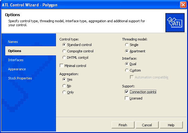
Figure 7: ATL Control Wizard, Options page.
You can also make the control insertable, which means it can be embedded into applications that support embedded objects, such as Excel or Word.
To make the control insertable
-
Click Appearance to open the Appearance page.
-
Select the Insertable check box, which by default will be cleared.

Figure 8: ATL Control Wizard, Appearance page.
The polygon displayed by the object will have a solid fill color, so you need to add a Fill Color stock property.
To add a Fill Color stock property and create the control
-
Click Stock Properties to open the Stock Properties page.
-
Under Not supported, scroll down the list of possible stock properties. Double-click Fill Color to move it to the Supported list:

Figure 9: ATL Control Wizard, Stock Properties page.
-
This completes the options for the control. Click Finish.
As the wizard created the control, several code changes and file additions occurred. The following files were created:
|
File |
Description |
|
PolyCtl.h |
Contains most of the implementation of the C++ class CPolyCtl. |
|
PolyCtl.cpp |
Contains the remaining parts of CPolyCtl. |
|
PolyCtl.rgs |
A text file that contains the registry script used to register the control. |
|
PolyCtl.htm |
A Web page containing a reference to the newly created control. |
|
Table 3. |
|
The wizard also performed the following code changes:
-
Added an #include statement to the stdafx.h and stdafx.cpp files to include the ATL files necessary for supporting controls.
-
Changed Polygon.idl to include details of the new control.
-
Added the new control to the object map in Polygon.cpp.
Now you can build the control to see it in action.
Building and Testing the Control
To build and test the control
-
On the Build menu, click Build Polygon.
 |
Figure 10: Building Polygon project.
-
Once the control finishes building, double-click PolyCtl.htm in Solution Explorer. The HTML Web page containing the control will be displayed. You should see a rectangle and the text ATL 7.0 : PolyCtl. This is your control.

Figure 11: Polygon project output.
Note: When completing this tutorial, if you receive an error message where the DLL file cannot be created, close the PolyCtl.htm file and the ActiveX Control Test container and build the solution again. If you still cannot create the DLL, reboot the computer or log off (if you are using Terminal Services).
Next, you will add a custom property to the control.
Step 3: Adding a Property to the Control
IPolyCtl is the interface that contains the control's custom methods and properties, and you will add a property to it.
To add a property using the Add Property Wizard
-
Right-click IPolyCtl in Class View (expand the Polygon branch to find it).
-
On the shortcut menu, click Add, and then click Add Property. The Add Property Wizard will appear.
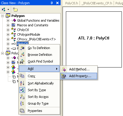
Figure 12: Adding property to project.
-
In the drop-down list of property types, select SHORT.
-
Type Sides as the Property name:

Figure 13: Add Property Wizard, Names page.
-
Click Finish to finish adding the property.
When you add the property to the interface, MIDL (the program that compiles .idl files) defines a Get method for retrieving its value and a Put method for setting a new value. The methods are named by prepending put_ and get_ to the property name.
The Add Property Wizard adds the necessary lines to the .idl file. It also adds the Get and Put function prototypes to the class definition in PolyCtl.h and adds an empty implementation to PolyCtl.cpp. You can check this by opening PolyCtl.cpp and looking for the functions get_Sides() and put_Sides(). Although you now have skeleton functions to set and retrieve the property, it needs a place to be stored. You will create a variable to store the property and update the functions accordingly.
To create a variable to store the property, and update the put and get methods
-
From Solution Explorer, open PolyCtl.h and add the following line at the end of the class definition, after the definition of m_clrFillColor:
short m_nSides;
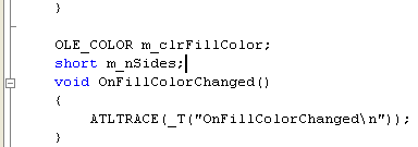
Listing 1.
-
Set the default value of m_nSides. Make the default shape a triangle by adding a line to the constructor in PolyCtl.h:
CPolyCtl()
{
m_nSides = 3;
}

Listing 2.
-
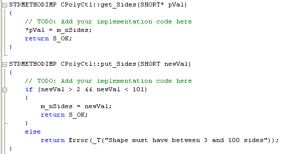
Implement the Get and Put methods. The get_Sides() and put_Sides() function declarations have been added to PolyCtl.h. Add the following code to PolyCtl.cpp to complete both methods:
STDMETHODIMP CPolyCtl::get_Sides(short *pVal)
{
*pVal = m_nSides;
return S_OK;
}
STDMETHODIMP CPolyCtl::put_Sides(short newVal)
{
if (newVal > 2 && newVal < 101)
{
m_nSides = newVal;
return S_OK;
}
else
return Error(_T("Shape must have between 3 and 100 sides"));
}
Listing 3.
The get_Sides() method returns the current value of the Sides property through the pVal pointer. In the put_Sides() method, the code ensures the user is setting the Sides property to an acceptable value. The minimum must be 2, and because an array of points will be used for each side, 100 is a reasonable limit for a maximum value.
You now have a property called Sides. In the next step, you will change the drawing code to use it.
Step 4: Changing the Drawing Code
By default, the control's drawing code displays a square and the text ATL 7.0 : PolyCtl. In this step, you will change the code to display something more interesting. The following tasks are involved:
-
Modifying the Header File.
-
Modifying the OnDraw() Function.
-
Adding a Method to Calculate the Polygon Points.
-
Initializing the Fill Color.
Modifying the Header File
Start by adding support for the math functions sin and cos, which will be used calculate the polygon points, and by creating an array to store positions.
To modify the header file
-
Add the line #include <math.h> to the top of PolyCtl.h:
#include <math.h>
#include "resource.h" // main symbols
-------------------------------------------------------------------------

Listing 4.
-
Once the polygon points are calculated, they will be stored in an array of type POINT, so add the array to the end of the class definition in PolyCtl.h:
OLE_COLOR m_clrFillColor;
short m_nSides;
POINT m_arrPoint[100];
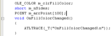
Listing 5.
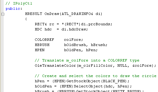
Modifying the OnDraw() Method
Now you should modify the OnDraw() method in PolyCtl.h. The code you will add creates a new pen and brush with which to draw your polygon, and then calls the Ellipse() and Polygon() Win32 API functions to perform the actual drawing.
To modify the OnDraw() function
-
Replace the existing OnDraw() method in PolyCtl.h with the following code:
HRESULT CPolyCtl::OnDraw(ATL_DRAWINFO& di)
{
RECT& rc = *(RECT*)di.prcBounds;
HDC hdc = di.hdcDraw;
COLORREF colFore;
HBRUSH hOldBrush, hBrush;
HPEN hOldPen, hPen;
// Translate m_colFore into a COLORREF type
OleTranslateColor(m_clrFillColor, NULL, &colFore);
// Create and select the colors to draw the circle
hPen = (HPEN)GetStockObject(BLACK_PEN);
hOldPen = (HPEN)SelectObject(hdc, hPen);
hBrush = (HBRUSH)GetStockObject(WHITE_BRUSH);
hOldBrush = (HBRUSH)SelectObject(hdc, hBrush);
Ellipse(hdc, rc.left, rc.top, rc.right, rc.bottom);
// Create and select the brush that
// will be used to fill the polygon
hBrush = CreateSolidBrush(colFore);
SelectObject(hdc, hBrush);
CalcPoints(rc);
Polygon(hdc, &m_arrPoint[0], m_nSides);
// Select back the old pen and
// brush and delete the brush we created
SelectObject(hdc, hOldPen);
SelectObject(hdc, hOldBrush);
DeleteObject(hBrush);
return S_OK;
}
Listing 6.
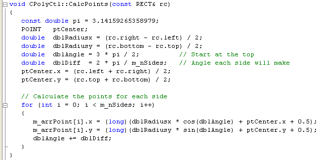
Adding a Method to Calculate the Polygon Points
Add a method, called CalcPoints(), that will calculate the coordinates of the points that make up the perimeter of the polygon. These calculations will be based on the RECT variable that is passed into the function.
To add the CalcPoints() method
-
Add the declaration of CalcPoints() to the IPolyCtl public section of the CPolyCtl class in PolyCtl.h:
void CalcPoints(const RECT& rc);
The last part of the public section of the CPolyCtl class will look like this:
void FinalRelease()
{ }
STDMETHOD(get_Sides)(short* pVal);
STDMETHOD(put_Sides)(short newVal);
void CalcPoints(const RECT& rc);

Listing 7.
-
Add this implementation of the CalcPoints() function to the end of PolyCtl.cpp:
void CPolyCtl::CalcPoints(const RECT& rc)
{
const double pi = 3.14159265358979;
POINT ptCenter;
double dblRadiusx = (rc.right - rc.left) / 2;
double dblRadiusy = (rc.bottom - rc.top) / 2;
double dblAngle = 3 * pi / 2; // Start at the top
double dblDiff = 2 * pi / m_nSides; // Angle each side will make
ptCenter.x = (rc.left + rc.right) / 2;
ptCenter.y = (rc.top + rc.bottom) / 2;
// Calculate the points for each side
for (int i = 0; i < m_nSides; i++)
{
m_arrPoint[i].x = (long)(dblRadiusx * cos(dblAngle) + ptCenter.x + 0.5);
m_arrPoint[i].y = (long)(dblRadiusy * sin(dblAngle) + ptCenter.y + 0.5);
dblAngle += dblDiff;
}
}
Listing 8.
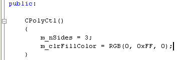
Initializing the Fill Color
Initialize m_clrFillColor with a default color.
To initialize the fill color
-
Use green as the default color by adding this line to the CPolyCtl constructor in PolyCtl.h:
m_clrFillColor = RGB(0, 0xFF, 0);
The constructor now looks like this:
CPolyCtl()
{
m_nSides = 3;
m_clrFillColor = RGB(0, 0xFF, 0);
}
Listing 9.
Building and Testing the Control
Rebuild the control. Make sure the PolyCtl.htm file is closed if it is still open, and then click Build Polygon on the Build menu. You could view the control once again from the PolyCtl.htm page, but this time use the ActiveX Control Test Container. If you fail to rebuild Polygon, save your solution, close Visual Studio, then delete Debug directory under the Polygon directory. Reopen Visual Studio and Polygon solution. Rebuild Polygon.
To use the ActiveX Control Test Container
-
On the Tools menu, click ActiveX Control Test Container.

Figure 14: Testing ATL object in ActiveX Control Test Container.
-
In Test Container, on the Edit menu, click Insert New Control.

Figure 15: Inserting new control, Polygon to ActiveX Control Test Container.
-
Locate your control, which will be called PolyCtl Class, and click OK. You will see a green triangle within a circle.
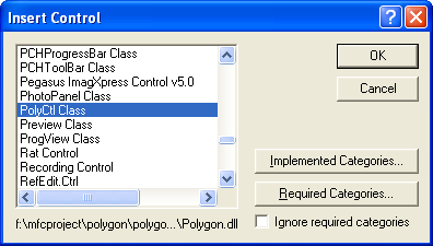
Figure 16: Selecting PolyCtl, an ATL control.

Figure 17: Polygon, an ATL control in action.
Try changing the number of sides by following the next procedure. To modify properties on a dual interface from within Test Container, use Invoke() Methods.
To modify a control's property from within the Test Container
-
In Test Container, click Invoke Methods on the Control menu. The Invoke Method dialog box is displayed:

Figure 18: Invoking the Polygon’s method.
-
Select the PropPut version of the Sides property from the Method Name drop-down list box.
-
Type 5 in the Parameter Value box, click Set Value, and click Invoke.
Note that the control does not change. Although you changed the number of sides internally by setting the m_nSides variable, this did not cause the control to repaint. If you switch to another application and then switch back to Test Container, you will find that the control has repainted and has the correct number of sides.
To correct this problem, add a call to the FireViewChange() function, defined in IViewObjectExImpl, after you set the number of sides. If the control is running in its own window, FireViewChange() will call the InvalidateRect() method directly. If the control is running windowless, the InvalidateRect() method will be called on the container's site interface. This forces the control to repaint itself.
To add a call to FireViewChange()
-
Update PolyCtl.cpp by adding the call to FireViewChange() to the put_Sides method. When you have finished, the put_Sides method should look like this:
STDMETHODIMP CPolyCtl::put_Sides(short newVal)
{
if (newVal > 2 && newVal < 101)
{
m_nSides = newVal;
FireViewChange();
return S_OK;
}
else
return Error(_T("Shape must have between 3 and 100 sides"));
}

Listing 10.
After adding FireViewChange(), rebuild and try the control again in the ActiveX Control Test Container. This time when you change the number of sides and click Invoke, you should see the control change immediately.
In the next step, you will add an event.

Figure 19: Polygon, an ATL control in action.
Further reading and digging:
-
MSDN MFC 9.0 class library online documentation - latest version.
-
DCOM at MSDN.
-
COM+ at MSDN.
-
COM at MSDN.
-
Unicode and Multi-byte character set: Story and program examples.