| Tenouk C & C++ | MFC Home | Event Handling, Mapping Modes, and a Scrolling View 1 | Basic Event Handling, Mapping Modes, and a Scrolling View 3 | Download | Site Index |
Module 3a:
Basic Event Handling, Mapping Modes, and a Scrolling View 2
This is a continuation from the previous module... Program examples compiled using Visual C++ 6.0 (MFC 6.0) compiler on Windows XP Pro machine with Service Pack 2. Topics and sub topics for this Tutorial are listed below:
Using AppWizard and ClassWizard Together
The following steps show how you use AppWizard and ClassWizard together to create this application:
Run AppWizard to create MYMFC1 project. Use AppWizard to generate an SDI project named MYMFC1 in the \mfcproject\mymfc1 subdirectory or any subdirectory that you have selected during the new project creation. The options and the default class names are shown here.

Figure 2: AppWizard MYMFC1 project summary.
Add the m_rectEllipse and m_nColor data members to CMymfc1View. With the Workspace window set to ClassView, right-click the CMymfc1View class, select Add Member Variable…, and then insert the following two data members:
private:
CRect m_rectEllipse;
int m_nColor;

Figure 3: Adding Member Variable through the ClassView.

Figure 4: The variable type and name.
If you prefer, you could type the above code inside the class declaration in the file mymfc1View.h.
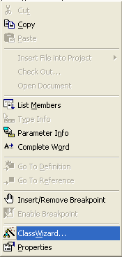
Use ClassWizard to add a CMymfc1View class message handler. Choose ClassWizard from the View menu of Visual C++, or right-click inside a source code window and choose ClassWizard from the context menu. Both shown below.
|
|
Figure 5: Invoking the ClassWizard through the View menu.
Figure 6: Invoking the ClassWizard through the context menu. |

When the MFC ClassWizard dialog appears, be sure that the CMymfc1View class is selected, as shown in the illustration below. Now click on CMymfc1View at the top of the Object IDs list box, and then scroll down past the virtual functions in the Messages list box and double-click on WM_LBUTTONDOWN. The OnLButtonDown() function name should appear in the Member Functions list box, and the message name should be displayed in bold in the Messages list box. Here's the ClassWizard dialog box.

Figure 7: ClassWizard dialog.
Instead of using ClassWizard, you can map the function from the Visual C++ WizardBar.
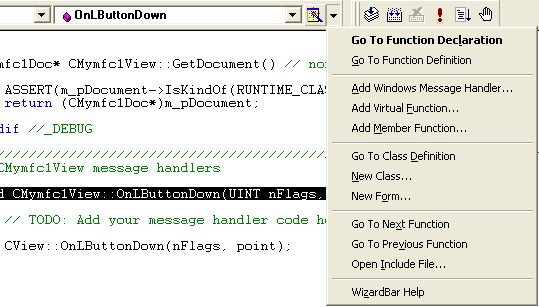
Figure 8: The WizardBar.
Edit the OnLButtonDown() code in mymfc1View.cpp. Click the Edit Code button in the ClassWizard dialog box. ClassWizard opens an edit window for mymfc1View.cpp in Visual C++ and positions the cursor on the newly generated OnLButtonDown() member function. The following replaces the previous code:
void CMymfc1View::OnLButtonDown(UINT nFlags, CPoint point)
{
if (m_rectEllipse.PtInRect(point))
{
if (m_nColor == GRAY_BRUSH)
{
m_nColor = WHITE_BRUSH;
}
else
{
m_nColor = GRAY_BRUSH;
}
InvalidateRect(m_rectEllipse);
}
}

Listing 2: C++ code segment.
Edit the constructor and the OnDraw() function in mymfc1View.cpp. The following replaces the previous code:
CMymfc1View::CMymfc1View() : m_rectEllipse(0, 0, 200, 200)
{
m_nColor = GRAY_BRUSH;
}
.
.
.
void CMymfc1View::OnDraw(CDC* pDC)
{
pDC->SelectStockObject(m_nColor);
pDC->Ellipse(m_rectEllipse);
}
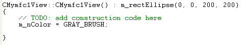
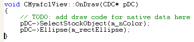
Listing 3: C++ code segment.
Build and run the MYMFC1 program. Choose
Build Mymfc1.exe from the Build
menu, or, on the Build toolbar,
click the
![]() button. Then choose Execute Mymfc1.exe
from the Build menu or, on the
Build toolbar, click the
button. Then choose Execute Mymfc1.exe
from the Build menu or, on the
Build toolbar, click the
![]() button. The resulting program responds to presses of the left mouse button by
changing the color of the circle in the view window. Don't press the mouse's
left button too quickly in succession; Windows interprets this as a double click
rather than two single clicks.
button. The resulting program responds to presses of the left mouse button by
changing the color of the circle in the view window. Don't press the mouse's
left button too quickly in succession; Windows interprets this as a double click
rather than two single clicks.
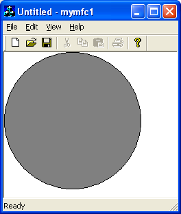
Figure 9: MYMFC1 program output.
Up to now, your drawing units have been display pixels, also known as device coordinates. The MYMFC1 drawing units are pixels because the device context has the default mapping mode, MM_TEXT, assigned to it. The statement:
pDC->Rectangle(CRect(0, 0, 200, 200));
draws a square of 200-by-200 pixels, with its top-left corner at the top left of the window's client area. The positive y values increase as you move down the window. This square would look smaller on a high-resolution display of 1024-by-768 pixels than it would look on a standard VGA display that is 640-by-480 pixels, and it would look tiny if printed on a laser printer with 600-dpi resolution. Try MYMFC1's Print Preview feature to see for yourself.
|
Figure 10: Print preview of the MYMFC1 project. |

What if you want the square to be 4-by-4 centimeters (cm), regardless of the display device? Windows provides a number of other mapping modes, or coordinate systems that can be associated with the device context. Coordinates in the current mapping mode are called logical coordinates. If you assign the MM_HIMETRIC mapping mode, for example, a logical unit is 1/100 millimeter (mm) instead of 1 pixel. In the MM_HIMETRIC mapping mode, the y axis runs in the opposite direction to that in the MM_TEXT mode: y values decrease as you move down. Thus, a 4-by-4-cm square is drawn in logical coordinates this way:
pDC->Rectangle(CRect(0, 0, 4000, -4000));
Looks easy, doesn't it? Well, it isn't, because you can't work only in logical coordinates. Your program is always switching between device coordinates and logical coordinates, and you need to know when to convert between them. This section gives you a few rules that could make your programming life easier. First you need to know what mapping modes Windows gives you.
The MM_TEXT Mapping Mode
At first glance, MM_TEXT appears to be no mapping mode at all, but rather another name for device coordinates. Almost. In MM_TEXT, coordinates map to pixels, values of x increase as you move right, and values of y increase as you move down, but you're allowed to change the origin through calls to the CDC functions SetViewportOrg() and SetWindowOrg(). Here's some code that sets the window origin to (100, 100) in logical coordinate space and then draws a 200-by-200-pixel square offset by (100, 100). An illustration of the output is shown in the following Figure. The logical point (100, 100) maps to the device point (0, 0). A scrolling window uses this kind of transformation.
void CMyView::OnDraw(CDC* pDC)
{
pDC->SetMapMode(MM_TEXT);
pDC->SetWindowOrg(CPoint(100, 100));
pDC->Rectangle(CRect(100, 100, 300, 300));
}
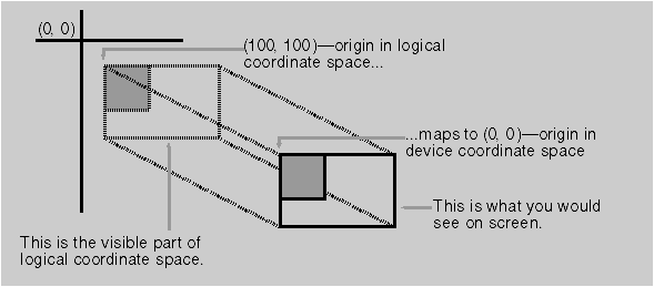
Figure 11: A square drawn after the origin has been moved to (100, 100).
The Fixed-Scale Mapping Modes
One important group of Windows mapping modes provides fixed scaling. You have already seen that, in the MM_HIMETRIC mapping mode, x values increase as you move right and y values decrease as you move down. All fixed mapping modes follow this convention, and you can't change it. The only difference among the fixed mapping modes is the actual scale factor, listed in the table shown here.
|
Mapping Mode |
Logical Unit |
|
MM_LOENGLISH |
0.01 inch |
|
MM_HIENGLISH |
0.001 inch |
|
MM_LOMETRIC |
0.1 mm |
|
MM_HIMETRIC |
0.01 mm |
|
MM_TWIPS |
1/1440 inch |
|
Table 2. |
|
The last mapping mode, MM_TWIPS, is most often used with printers. One twip unit is 1/20 point. A point is a type measurement unit. In Windows it equals exactly 1/72 inch. If the mapping mode is MM_TWIPS and you want, for example, 12-point type, set the character height to 12 × 20, or 240, twips.
The Variable-Scale Mapping Modes
Windows provides two mapping modes, MM_ISOTROPIC and MM_ANISOTROPIC that allow you to change the scale factor as well as the origin. With these mapping modes, your drawing can change size as the user changes the size of the window. Also, if you invert the scale of one axis, you can "flip" an image about the other axis and you can define your own arbitrary fixed-scale factors. With the MM_ISOTROPIC mode, a 1:1 aspect ratio is always preserved. In other words, a circle is always a circle as the scale factor changes. With the MM_ANISOTROPIC mode, the x and y scale factors can change independently. Circles can be squished into ellipses. Here's an OnDraw() function that draws an ellipse that fits exactly in its window:
void CMyView::OnDraw(CDC* pDC)
{
CRect rectClient;
GetClientRect(rectClient);
pDC->SetMapMode(MM_ANISOTROPIC);
pDC->SetWindowExt(1000, 1000);
pDC->SetViewportExt(rectClient.right, -rectClient.bottom);
pDC->SetViewportOrg(rectClient.right / 2, rectClient.bottom / 2);
pDC->Ellipse(CRect(-500, -500, 500, 500));
}
The functions SetWindowExt() and SetViewportExt() work together to set the scale, based on the window's current client rectangle returned by the GetClientRect() function. The resulting window size is exactly 1000-by-1000 logical units. The SetViewportOrg() function sets the origin to the center of the window. Thus, a centered ellipse with a radius of 500 logical units fills the window exactly, as illustrated in the following Figure.

Figure 12: A centered ellipse drawn in the MM_ANISOTROPIC mapping mode.
Here are the formulas for converting logical units to device units:
-
x scale factor = x viewport extent / x window extent
-
y scale factor = y viewport extent / y window extent
-
device x = logical x × x scale factor + x origin offset
-
device y = logical y × y scale factor + y origin offset
Suppose the window is 448 pixels wide (rectClient.right). The right edge of the ellipse's client rectangle is 500 logical units from the origin. Then:
-
The x scale factor is 448/1000, and
-
The x origin offset is 448/2 device units.
If you use the formulas shown previously, the right edge of the ellipse's client rectangle comes out to 448 device units, the right edge of the window. The x scale factor is expressed as a ratio (viewport extent/window extent) because Windows device coordinates are integers, not floating-point values. The extent values are meaningless by themselves. If you substitute MM_ISOTROPIC for MM_ANISOTROPIC in the preceding example, the "ellipse" is always a circle, as shown in the following Figure. It expands to fit the smallest dimension of the window rectangle.

Figure 13: A centered ellipse drawn in the MM_ISOTROPIC mapping mode.
Coordinate Conversion
Once you set the mapping mode (plus the origin) of a device context, you can use logical coordinate parameters for most CDC member functions. If you get the mouse cursor coordinates from a Windows mouse message (the point parameter in OnLButtonDown()), for example, you're dealing with device coordinates. Many other MFC functions, particularly the member functions of class CRect, work correctly only with device coordinates. The CRect arithmetic functions use the underlying Win32 RECT arithmetic functions, which assume that right is greater than left and bottom is greater than top. A rectangle (0, 0, 1000, -1000) in MM_HIMETRIC coordinates, for example, has bottom less than top and cannot be processed by functions such as CRect::PtInRect unless your program first calls CRect::NormalizeRect, which changes the rectangle's data members to (0, -1000, 1000, 0).
Furthermore, you're likely to need a third set of coordinates that we will call physical coordinates. Why do you need another set? Suppose you're using the MM_LOENGLISH mapping mode in which a logical unit is 0.01 inch, but an inch on the screen represents a foot (12 inches) in the real world. Now suppose the user works in inches and decimal fractions. A measurement of 26.75 inches translates to 223 logical units, which must be ultimately translated to device coordinates. You will want to store the physical coordinates as either floating-point numbers or scaled long integers to avoid rounding-off errors. For the physical-to-logical translation you're on your own, but the Windows GDI takes care of the logical-to-device translation for you. The CDC functions LPtoDP() and DPtoLP() translate between the two systems, assuming the device context mapping mode and associated parameters have already been set. Your job is to decide when to use each system. Here are a few rules of thumb:
-
Assume that the CDC member functions take logical coordinate parameters.
-
Assume that the CWnd member functions take device coordinate parameters.
-
Do all hit-test operations in device coordinates. Define regions in device coordinates. Functions such as CRect::PtInRect work best with device coordinates.
-
Store long-term values in logical or physical coordinates. If you store a point in device coordinates and the user scrolls through a window, that point is no longer valid.
Suppose you need to know whether the mouse cursor is inside a rectangle when the user presses the left mouse button. The code is shown here.
// m_rect is CRect data member of the derived view class with
// MM_LOENGLISH logical coordinates
void CMyView::OnLButtonDown(UINT nFlags, CPoint point)
{
CRect rect = m_rect; // rect is a temporary copy of m_rect.
CClientDC dc(this); // This is how we get a device context
// for SetMapMode and LPtoDP
// -- more in next module
dc.SetMapMode(MM_LOENGLISH);
dc.LPtoDP(rect); // rect is now in device coordinates
if (rect.PtInRect(point))
{
TRACE("Mouse cursor is inside the rectangle.\n");
}
}
The TRACE is a macro. As you'll soon see, it's better to set the mapping mode in the virtual CView function OnPrepareDC() instead of in the OnDraw() function.
Continue on next module....part 3
Further reading and digging:
-
MSDN MFC 9.0 class library online documentation - latest version.
-
DCOM at MSDN.
-
COM+ at MSDN.
-
COM at MSDN.
-
Unicode and Multi-byte character set: Story and program examples.