|Winsock & .NET |Winsock | < Linux Socket Index | TCP/IP Client Server Model > |
NETWORK PROGRAMMING
LINUX SOCKET PART I: THE FUNDAMENTALS
Menu
Network Story 1Network Story 2Network Story 3Network Story 4Network Story 5Network Story 6Socket Example 1Socket Example 2Socket Example 3Socket Example 4Socket Example 5Socket Example 6Socket Example 7Advanced TCP/IP 1Advanced TCP/IP 2Advanced TCP/IP 3Advanced TCP/IP 4Advanced TCP/IP 5
Advanced Winsock2 Tutorial | My Training Period: xx hours
Note: Program examples if any, compiled usinggcc on Linux Fedora Core 3 machine with several update, as normal user. The Fedora machine used for the testing having the "No Stack Execute" disabled and the SELinux set to default configuration.
The abilities that supposed to be acquired:
This Tutorial introduces a network programming using sockets. Some of the information is implementation specific but all the program examples run on Fedora 3 and compiled using gcc. The following are topics that will be covered briefly.
Some Background Story
Figure 1
|
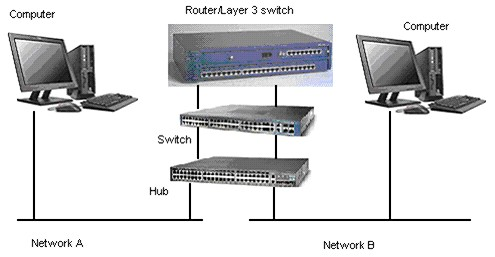
Using a simple network shown in the above Figure, let trace the data stream flow from Network A to Network B, by assuming that Network A is company A’s network and Network B is company B’s network.
Physically, the flow of the data stream is from a computer in Network A (source) will go through the hub, switch and router.
Then the stream travel through the carrier such as Public Switch Telephone Network (PSTN) and leased line (copper, fiber or wireless – satellite) and finally reach Network B’s router, go through the switch, hub and finally reach at the computer in company B (destination).
And from the previous network devices layout, the OSI (Open System Interconnection) 7 layer stack mapping is shown below.

Figure 2
From the Application layer of a computer at company A go downward the layer until the Physical (medium such as Cat 5 cable) layer, then exit Network A through the Network (router) layer in the middle of the diagram.
After traveling through the carrier, reaches at the Network (router) layer of company B, travels through the Physical layer, goes upward until reaching at the Application layer of the computer at company B. Actually, at company B (the destination), the data flows through the network devices in the reverse manner compared to what happened at company A (the source).
In contrast to TCP/IP, the OSI approach started from a clean slate and defined standards, adhering tightly to their own model, using a formal committee process without requiring implementations.
Internet protocols use a less formal but more practical engineering approach, where anybody can propose and comment on Request For Comment (RFC) documents, and implementations are required to verify feasibility.
The OSI protocols developed slowly, and because running the full protocol stack is resource intensive, they have not been widely deployed, especially in the desktop and small computer market.
In the meantime, TCP/IP and the internet were developing rapidly, with deployment occurring at a very high rate, which is why the TCP/IP suite becomes a de facto standard.
The OSI layer and their brief functionalities are listed in the following Table.
OSI Layer | Function provided |
Application | Network application such as file transfer and terminal emulation |
Presentation | Data formatting and encryption. |
Session | Establishment and maintenance of sessions. |
Transport | Provision for end-to-end reliable and unreliable delivery. |
Network | Delivery of packets of information, which includes routing. |
Data Link | Transfer of units of information, framing and error checking. |
Physical | Transmission of binary data of a medium. |
Table 1 | |
In the practical implementation, the standard used is based on TCP/IP stack. This TCP/IP stack is a de facto standard, not a pure standard but it is widely used and adopted.
The equivalent or mapping of the OSI and TCP/IP stack is shown below. It is divided into 4 layers. The Session, Presentation and Application layers of OSI have been combined into one layer, Application layer.
Physical and data link layers also become one layer. Different books or documentations might use different terms, but the 4 layers of TCP/IP are usually referred.

Figure 3
In this Tutorial we will concentrate more on the Transport and Network layer of the TCP/IP stack.
More detail TCP/IP stack with typical applications is shown below.

Figure 4
The following figure is a TCP/IP architectural model. Frame, packet and message are same entity but called differently at the different layer because there are data encapsulations at every layer.
|

Figure 5
The common applications that you encounter in your everyday use are:
FTP (file transfer protocol).
SMTP (simple mail transfer protocol).
telnet (remote logins).
rlogin (simple remote login between UNIX machines).
World Wide Web (built on http) and https (secure http).
NFS (network filing system – originally for Sun Microsystems).
TFTP (trivial file transfer protocol – used for booting).
SNMP (simple network management protocol).
The user interfaces developed (programs) for the communication should depend on the platform.
Protocol
In computing field, a protocol is a convention or standard rules that enables and controls the connection, communication and data transfer between two computing endpoints.
Protocols may be implemented by hardware, software, or a combination of the two. At the lowest level, a protocol defines the behavior of a hardware connection.
In term of controls, protocol may provide data transfer reliability, resiliency and integrity.
An actual communication is defined by various communication protocols. In the context of data communication, a network protocol is a formal set of rules, conventions and data structure that governs how computers and other network devices exchange information over a network.
In other words, protocol is a standard procedure and format that two data communication devices must understand, accept and use to be able to talk to each other.
A wide variety of network protocols exist, which are defined by many standard organizations worldwide and technology vendors over years of technology evolution and developments. One of the most popular network protocol suites is TCP/IP, which is the heart of internetworking communications.
TCP and UDP Protocols
TCP and UDP protocols were built on top of the IP protocol.
Basic for the TCP:
Transmission Control Protocol is defined byRFC-793.
TCP provides connection-oriented transport service and reliable.
End-to-end transparent byte-stream.
E.g.: FTP, telnet, http, SMTP.
While the UDP:
User Datagram Protocol is defined byRFC-768.
UDP provides datagram service that is a packet based.
Connectionless.
Unreliable.
E.g.: NFS, TFTP.
Port numbers and services
It is 16 bit integers. So we have 216 = 65536 ports maximum.
It is unique within a machine/IP address. Every service/application/daemon will have their own port number.
To make a connection we need an IP address and port number of the protocol.
The connection defined by:
IP address & port of server + IP address & port of client
Normally, server port numbers are low numbers in the range 1 – 1023, normally calledwell known port number and normally assign for root (Administrator) only.
It is used for authentication e.g. rlogin.
And normally, client port numbers are higher numbers starting at 1024.
A server running on a well-known port lets the OS know what port it wants to listen on.
Whereas a client normally simply lets the operating system picks a new port that isn’t already in use.
Numeric IP Addresses
Ipv4 (Internet Protocol version 4) Internet address is 32 bit integers. The IP stand for Internet Protocol.
For convenience they are displayed in "dotted decimal" format.
Each byte is presented as a decimal number.
Dots separate the bytes, for example:
131.95.115.204
IP Address Classes
To simplify packet routing, internet addresses are divided into classes.
An IP address has two parts: The network portion and the host portion.
The network portion is unique to each company/organization/domain/group/network, and the host portion is unique to each network device (host) in the network.
Where the network portion ends and the host portion begin is different for each class of IP address.
You can determine this by looking at the two high-order bits in the IP address.
192.168.1.100 | |||
xxxxxxxx.xxxxxxxx.xxxxxxxx.xxxxxxxx Byte 1.Byte 2.Byte 3.Byte 4 | |||
Class and Network size | Range (decimal) | Network ID | Host ID |
Class A (Large) | 1 -127 | Byte 1 | Bytes 2, 3, 4 |
Class B (Medium) | 128 – 191 | Bytes 1, 2 | Bytes 3, 4 |
Class C (Small) | 192 – 223 | Bytes 1, 2, 3 | Bytes 4 |
Table 2 | |||
The first four bits (bits 0-3) of an address determine its class:
0xxx = class A - bits 1-7 define a network. bits 8-31 define a host on that network. So we've128 networks with 16 million hosts. |
10xx = class B - bits 2-15 define a network. bits 16-31 define a host on that network. So we've 16384 networks with 65536 hosts. |
110x = class C - bits 3-23 define a network. bits 24-31 define a host on that network. So we've 2 million networks with 256 hosts. |
Table 3 |
The IP network portion can represent a very large network that may spans multiple geographic sites.
To make this situation easier to manage, you can use subnetworks. Subnetworks use the two parts of the address to define a set of IP addresses that are treated as group. The subnetting divides the address into smaller networks.
You configure a subnetwork by defining a mask, which is a series of bits. Then, the system performs a logical AND operation on these bits and the IP address.
The 1 bit defines the subnetwork portion of the IP address (which must include at least the network portion). The 0 bits define the host portion.
Class D is a multicast address and class E is reserved.
As a summary:

Figure 6
Nowadays we use classless IP address. That means we subnet the class type IP into smaller subnet or smaller group of IP addresses creating smaller networks. The example can be found inClassless Inter-Domain Routing (CIDR) and the private domain normally uses theprivate IP range. The private IP range cannot be routed in the Internet domain.
A network technology that deploy the private IP isVirtual Private Network (VPN) while the advanced sub-netting technology using private IP can be found inVirtual LAN (VLAN).
Before the IPV4 run out of the IP addresses, now we have IPV6 with 128 bits.
Host Names and DNS
People need names to make it simpler to use the Internet instead of the dotted decimal.
The Domain Name System (DNS) can translate from name (domain name) to number (IP address) or from number to name. This is called name resolution.
Name resolution done by Domain Name Service (DNS – although the term is same as the Domain Name System and same acronym, this is Microsoft implementation of the Domain Name System) in Windows and in Unices/Linux it is implemented using Berkeley Internet Name Domain (BIND).
Ethernet Addresses
MAC and ARP protocol
In Local Area Network (LAN), based on the architecture, we have several network types such as Ethernet and Token Ring.
The most widely used is Ethernet.
Each Ethernet interface (Network Interface Card -NIC) has a unique Ethernet address provided by the manufacturer, hard coded into the NIC, normally called Media Access Control (MAC) or physical address.
Ethernet addresses are 6 bytes shown as 6 hexadecimal values separated by colons.
For example: 00:C0:F0:1F:3C:27.
You can see this MAC address by issuing the arp or ipconfig or ifconfig (Linux) command as shown below:
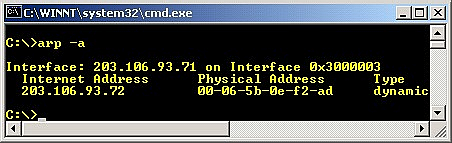
Figure 7

Figure 8
Ethernet packets have header and data sections.
The header contains the source and destination of the Ethernet addresses (MAC) and a 2 byte packet type.
For IP packets the data area contains the IP fields which hold the IP source and destination addresses that are readable and more suitable for human.
To send to an IP address, a computer uses the Address Resolution Protocol (arp) to determine a MAC address.
IPv6 - Internet Protocol version 6
Current IP is IPv4 (Internet Protocol version 4).
IPv4 has 32 bit addresses.
Due to splitting addresses, 32 bits is not enough.
IPv6 will have 128 bit addresses.
Addresses will be shown in a colon hexadecimal format with internal strings of 0s omitted. For example:
69DC:88F4:FFFF:0:ABCD:DBAC:1234:FBCD:A12B::F6
New service types exist to accommodate IPv6 such as in multimedia and wireless fields.
In Windows Xp and above, you can try the ipv6 command at the prompt to view and/or set the IPv6 configuration. For example: ipv6 if.

Figure 9

Figure 10
Distributed Applications
The goal is to hide the fact that the application is distributed other than to provide the redundancy for reliability.
User interfaces can look identical.
Typically data resides on remote systems.
In many instances, remote users interact with each other.
Application Protocols
Protocol is a set of rules defining how to communicate.
Application protocol: communication rules for an application.
Standard protocols: documented in RFCs such as ftp, telnet, http.
Non-standard protocols: programmers write a distributed application = new protocol.
Programmers choose standard protocols where they apply.
E.g. telnet:
telnet computer.some.where [port_number]
telnet www.yahoo.com 23
Port is a number defining which service to connect to.
For example, port 23 is the default for telnet services.
In Linux, ports, protocols and service names are specified in/etc/services.
We will learn more detail regarding the port, protocol and service another Modules.
Providing Concurrent Access to Services
Users expect almost immediate response.
Network servers must handle multiple clients "apparently simultaneously".
The CPU resources and network must be shared.
Normally in the form of multiple server's processes or multiple server'sthreads in one process.
…Continue on next Module…More in-depth discussion about TCP/IP suite is given inAdvanced TCP/IP Tutorials.
Further reading and digging: